Connection of instrument voltage and current transformers – practical guidance and instructions.
We measure high voltage for you
using instrument transformers for both outdoor and indoor applications, special transformers, sensors and power transformers
Connection of instrument voltage and current transformers
KPB Intra s.r.o.
Ing. Josef Stejskal
Experience with connection of instrument transformers indicates that not every installation company is completely clear on how to connect the converter in practice. Examples of correct connection, potential errors and their prevention are described below.
Instrument voltage transformers
It applies generally that a voltage transformer may not be operated till a short circuit and, if it takes place, an explosion follows very shortly after it. The explosion results in consequent damage of adjacent equipment.
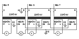
Connection of three earthed transformers with one measuring and one auxiliary winding should be done in accordance with the diagram in Fig. 1. Voltmeters are connected to the measuring windings (100/√3 V). One of the terminals is always earthed (“n” terminal here).
| Fig. 1 | Fig. 2 |
 |
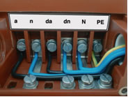 |
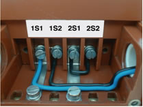
The auxiliary winding (100/3 V) is connected in a so-called “open triangle”. Unlike the preceding case, earthing is done at only one point here. For an example of connection in practice please see Fig. 2.
One of the errors of installation companies is earthing of an open triangle similarly as in the case of the measuring windings, i.e. one of the terminals of the secondary circuit is connected to the earth. However, earthing of not only the “da” terminal but also the “dn” terminal takes place here with respect to the character of connection and the transformers are operated until a short circuit occurs. An explosion occurs consequently.
Insufficient checking is another error that appears in practice. There are cases where one installation company performs connection of the measuring winding of transformers in accordance with Fig. 1, i.e. it applies earthing of the “n” terminal. This company only performs installation of transformers. Another company will connect voltmeters and use their earthing terminal for earthing. However, this terminal has already been connected with the “a” terminal of the transformer through the supply line. General connection is not verified by anybody. The instruments then operate until a short circuit occurs and an explosion is a matter of several seconds.
Instrument current transformers
A certain advantage of installation of current transformers is the fact that explosions do not occur in the case of an error in connection; however, damage of the instrument or risk for the operator may also occur here.
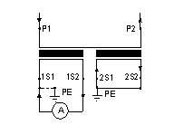
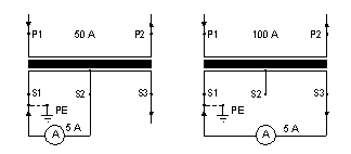
It applies generally that the secondary outlets are either connected to the burden or interconnected to the short circuit and one of the outlets is earthed. This principle is apparent from Fig. 3 and Fig. 5. Several errors are made in practice. Non-earthing one of secondary terminals may be one of them. Capacitive coupling is created then and the secondary circuit emits sparks on the frame. Conductive paths are created in the case of longer duration.
| Fig. 3 | Fig. 4 | Fig. 5 |
 |
 |
 |
Ambiguities with the switch-over type of transformer can be another source of errors. A correct example of connection is illustrated in Fig. 4. It is apparent here that one terminal always remains free. An error occurs if this terminal is earthed. The transformer stops measuring then.
The above described errors may be prevented using several methods. Primarily, installation must be carried out by competent persons with practise in the given field. If they have not required experience, they must study installation instructions attached to each instrument or catalogue documentation (see “Operation and installation instructions”). It is also necessary to perform inspection of a general circuit, i.e. not only operations performed by each individual company, but connection as a unit and its compliance with the design. After all, disconnection of wires and then measuring with an ohmmeter is sufficient for verification of earthing of terminals and burdens.
Practical experience with installation of converters, potential errors and methods of their rectification are described above.
We hope to contribute to understanding of issues and prevention of consequent potential damages by giving the explanation above.