Home > Support > The Instruction for the mounting and operation of the current instrument transformers
Support The Instruction for the mounting and operation of the current instrument transformers
We measure high voltage for you
using instrument transformers for both outdoor and indoor applications, special transformers, sensors and power transformers
The Instruction for the mounting and operation of the current instrument transformers
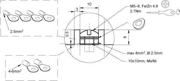
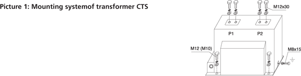
The mounting position of the instrument transformers CTS, CTT and CTB is arbitrary. The transformers CTSO 38 are mounted in the vertical position. The transformers are fixed by the means of four screws M10 (CTS 12) or M12 (CTS 25, CTS 25X, CTS 25X Sch, CTS 38, CTS 38X, CTS 38X Sch, CTSO 38, CTB 25, CTT 25) in the holes in the basic plate or in the profiles.The connection of the power circuit to the primary terminals is done by the means of the screws M12 (See picture No.1) with max. torque module 70Nm.We recommend use terminal ends corresponding to the used cross-section of the conductor (its maximum size is 10 mm2) for attaching to the secondary outlets.Metal functional parts of the transformer are coated against corrosion. The primary terminals are galvanized with nickel or silver-plated. The secondary terminals are galvanized with nickel. The basic plates are cold galvanized (transformers for the indoor settings) or hot galvanized (transformers for the outdoor settings).
We recommend clean transformers from dirt and draw close the connections in case of shut down.
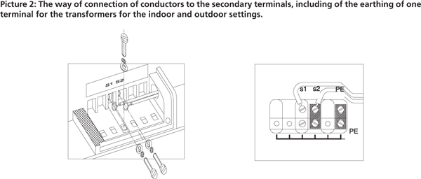
Before starting-up it is necessary to earth the metal base of transformer (earthling “cube” with screw M8x15 with max. torque module 10Nm see picture No. 1) and one secondary terminal of every outlet (See picture No. 2). The secondary outlets, that were not used, are necessary to be short connected and earthed (See the examples in pictures No. 3-5).The earthling of the secondary outlets is done by the means of screws M5x16 (max. torque 2.7 Nm) and jumpers (See picture No. 2) that arethe parts of the set of each supplied transformer.
|
Tightening torque max. |
Primary terminal M12 |
70 Nm |
Ground terminal M8 |
10 Nm |
Secondary terminal M5 |
2.7 Nm |
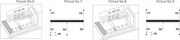
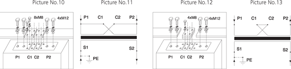
The construction of transformers allows the switching of the ranges on both the secondary and primary sides. The secondary switching is made by the means of switching of branches on the secondary coil. See the examples in picturesNo. 6-9. The primary switching has easy mounting, connecting two jumpers into the circuit by the means of screws M8 (both the screws and jumpers are the part of the set of the transformer). See the examples of interconnection inpictures No. 10-13.
The secondary terminal board is provided with the plastic cover with sealing cover and also, on the sides, with the threads Pg16 with screwed blinding and jumper for the drawing die of the secondary line-wires.The secondary terminal board of the transformers for the outdoor settings (type CTSO) is provided with the waterproofcover with sealing screw and waterproof bushing for the connection of the secondary line-wires.
The examples of circuit of the secondary terminal board of measuring current transformers, including special cases
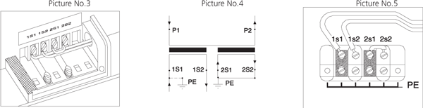
There is the example of circuit of two-cored transformer with ratio 50//5/5 A in the picture No. 3. The terminals of the fi rst secondary winding (symbols 1S1 and 1S2) are connected to the external load and one terminal (in this case 1S1) is earthed. The second secondary winding (symbols 2S1 and 2S2) is not connected to the external load and so the terminals have to be interconnected in the short circuit and they have to be earthed. The wiring diagram is in picture No. 4. The mounting of the terminal board is in picture No. 5.
The example of mounting of the secondary terminal board of one-core transformer with the ratio 50-100//5 A and with the switchingon the secondary side you can see in the following pictures. Picture No. 6 describes the connection for the ratio 50//5 A. Terminals S1 and S2 are brought out to the external load and one terminal (in this case S1) is earthed. The electric scheme is in picture No. 7. The mounting for the ratio 100/5 you can see in picture No. 8. Terminals S1 and S3 are brought out to the external load and terminal S1 has to stay earthed. Terminal S2 remains unassigned. Wiring diagram is in picture No. 9.
In the following case you can see the example of mounting of the primarily switchable transformer with the ratio 50-100//5 A. In picture No. 10 is shown the connection for the primary current of 100 A. Terminals P1, C1 and P2, C2 are interconnected by the means of the special connector and screws M8. Wiring diagram is in picture No. 11. The way of contacting for the primary current of 50 A is in picture No. 12. Terminals C1 and C2 are interconnected by the means of both connectors and screws M8. Scheme is in picture No. 13.
Note: The above-mentioned connections are recommended by the producer only in the caseswhere the expert designer does not determine other way.