Home > Support > The instruction for the mounting and operation of the voltage instrument transformers.
Support the instruction for the mounting and operation of the voltage instrument transformers.
We measure high voltage for you
using instrument transformers for both outdoor and indoor applications, special transformers, sensors and power transformers
The instruction for the mounting and operation of the voltage instrument transformers
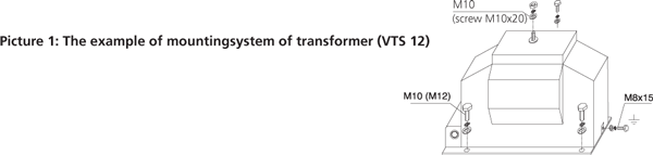
The mounting position of the instrument transformers VTS and VTD is arbitrary. The transformers VTO and VPT are only mounted in the vertical position. The transformers are fixed by the means of four screws M10 (VTS 12 and VTD 12) or M12 (VTS 25, VTS 38,VTD 25, VTO 38, and VTDOR 38) in the holes in the basic plate or in the profi les. The connection of high voltage to the primary side is recommended by the means of the terminal ends with 10 mm and screws M10 with max. torque module 20Nm. The example of mounting system of transformer is shown in picture No. 1 (VTS 12). For the contacting on thehigh voltage side of transformers with isolators we recommend to use the conductors of maximum diameter of 6 mm2 and terminal ends by the reason of springing of the dynamic forces within the system.ATTENTION: The isolators must not be pre-stressed mechanically in the direction away from the body of transformer during the mounting process.
We recommend clean transformers from dirt and draw close the connections in case of shut down.
Before starting-up it is necessary to earth the metal base of transformer (earthling “cube” with screw M8x15 with max.torque module 10Nm see picture No.1).
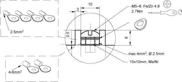
The earthling of the secondary outlets is done by the means of screws M5x16 (max. torque 2.7 Nm) and jumpers (See picture No.2) that are the parts of the set of each supplied transformer. The example of mounting is shown in picture No. 2.The construction of transformers allows the switching of the ranges on the secondary branches of transformer. The examples are shown on the following page.
The secondary terminal board is provided with the plastic cover with sealing cover and also, on the sides, with the threads Pg16 with screwed blinding and jumper for the drawing die of the secondary conductors.The secondary terminal board of the transformers for the outdoor settings (types VTO and VPT) is provided with the waterproofcover with sealing screw and waterproof bushing for the connection of the secondary conductors.
ATTENTION! It is necessary to check after each starting-up whether the secondary winding is not earthed by one terminal on the terminal board and by the second terminal by the outlet in the low voltage part. Otherwise the instrument is connected in short way and after the starting-up of high voltage the destruction of the instrument occurs.

The examples of circuit of the secondary terminal board of measuring voltage transformers,including special cases
Single-pole instrument transformers of type VTS for the use of three-phased, inefficiently earthed systems are usually provided withtwo secondary windings. The first of these windings is used for the measurement or protection, the second for signaling of earthconnection. They are linked up in three phases - the primary and secondary windings are star-connected, auxiliary winding in open triangle (See wiring diagram in picture No.3).
Terminal “N” of the primary winding, one terminal of the secondary winding and one of the end terminals of the open triangle have to be earthed during the operation. (ATTENTION! In case of earthling of the open triangle on two terminals there is the danger of instrument destruction.) The example of circuit of terminal board is shown in picture No. 4.

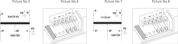
In the following case you can see the example of switchable single-poled transformer with the ratio 6600-11000/√3//100/√3 V.The switching is possible due to branch on the secondary winding. Picture No. 5 shows the scheme for the ratio /√3//100/√3 V. The measuring outlet is between the terminals a1 - n, terminal a2 remains unassigned. The mounting of terminal board is shown in picture No. 6. The scheme for the ratio 11000/√3//100/√3 V is shown in picture No. 7. The measuring outlet is here between terminals a2 - n, terminal a1 remains unassigned. The mounting of terminal board is shown in picture No. 8.
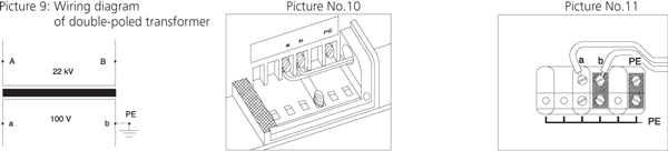
Double-poled instrument transformers VTD and VPT have all parts of primary winding, including terminals, isolated from earth. The isolation is dimensioned on the level of testing voltages according to the corresponding nominal voltage.One of the secondary terminals must be earthed during the operation (it is not the case of the so called “V- connection”). Wiring diagram of transformer is shown in picture No. 9. The connection of terminal board for indoor setting is shown in picture No. 10 and for outdoor setting in picture No. 11.
Note: The above-mentioned connections are recommended by the producer only in the cases where theexpert designer does not determine other way.