Home > Products > Current instrument transformers > Inside aplication > Instrument transformers CTS with voltage detector
CTS12, CTS 25 and CTS25X can be equipped with voltage detector hv. On principle it is made by coupling capacity
We measure high voltage for you
using instrument transformers for both outdoor and indoor applications, special transformers, sensors and power transformers
Instrument transformers CTS12, CTS 25 and CTS25X can be equipped with voltage detector hv. On principle it is made by coupling capacity (capacitor divider) which is moulded in epoxy machine casting. A voltage detector is connected to this by a special cable.
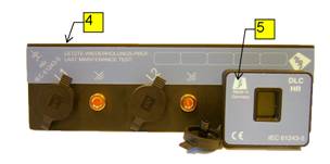
The function is determined by norm ČSN EN 61243-5. Voltage indication absent (detector’s LCD display is empty) is in the primary voltage area smaller than 10% Rv. (where Rv is voltage system that is e.g. 6,10,15,22 kV). Voltage system present (you can see letter “U” on LCD display) has to be in the area where primary voltage is higher than 45% Rv. In the area from 10% to 45%Rv the voltage indication present can be (but does not have to be) alight.
The VDS (voltage detection system) of HR class (high resistance) has been chosen for transformers CTS. Wiring (so-called “interface”) and other accessories (panel and detector) are made by GEORG JORDAN GMBH producer. The system has been put through exams according to ČSN EN 61243 and it is being delivered as a set.
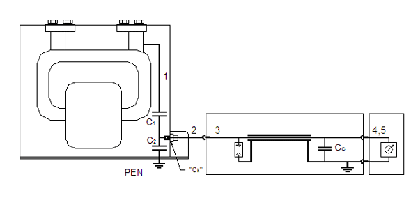
The system description (mounting procedure) is clear from picture 1
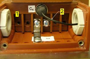
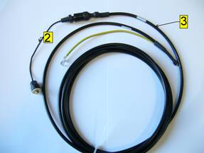
It consists of measuring transformer No. 1. There is a capacitator divider inside made by coupling (high-voltage) capacity C1 and low-voltage capacity C2. Reading voltage is brought out to the terminal Ck whis is placed in device’s secondary terminal board. It differs from other terminal by thread M6. The terminal of contact cable No. 2 is screwed into this (the follow-through force is determined by the slide of plastic terminal in metal tightening wrench. Its opposite end is plugged into cable interface connector No.3. The end of cable interface is then plugged into isolated terminal on detector panel No. 4. Earthing terminal of interface is then plugged into earthing terminal of panel as in picture No. 4. Detector No. 5 is then plugged into appropriate sockets as in picture 4.
The system can be used withing the temperature interval of -25°+ 50°C in internal environment. Cable No. 3 can be 3m or 6m long.
You have to specify the detector requirement, the length of cable and rated line voltage in the order: e.g.: transformer CTS 25X with voltage detector, system voltage 22kV, cable of interface 6m.
Instrument transformers CTS 12 are equipped by the indication within the range of voltage 6-15kV.
Instrument transformers CTS 25 and CTS 25X are equipped by the indication within the range of voltage 15-22 kV.
 |
 |
| Pic. nr. 2 | Pic. nr. 3 |
 |
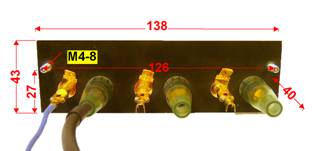 |
| Pic. nr. 4 | Pic. nr. 5 |
Set specification:
- current transformer with capacitator divider, C1 high-voltage capacity, C2 low-voltage capacity, “Ck” terminal of terminal lead of capacitator divider in secondary terminal board (thread M6)
- contact cable AK4 160mm thread M6“
- kcable of interface with the length of 3m (6m) with protective spark gap and its own capacity labeled as “coaxial lead 3M/303pF/HR (6M/303pF/HR)”
- detector panel (1 panel for 3 detectors) labeled as „interface point HR 3 phase GK“
- detector labeled as „continuous voltage indicator DLC HR“
Note: items 2,3,4 are produced by JORDAN GMBh company and they are part of KPB Intra’s complete delivery.