AFR 31 Smart Load to Reduce Ferroresonance
We measure high voltage for you
using instrument transformers for both outdoor and indoor applications, special transformers, sensors and power transformers
AFR 31
The AFR 31 Smart Load is an instrument designed to protect metering voltage transformers against adverse effects of ferroresonance in high voltage power distribution systems with ungrounded or indirectly grounded neutral wire. Ferroresonance comes up between transformer inductance and conductors’ or switching elements’ capacitance. Connecting, disconnecting, ground connection or other transitional effects may be the trigger events. Ferroresonance oscillations cause significant overvoltage and current surges as a result of transformer magnetic circuit saturation. This most often leads to metering transformer destruction.
AFR 1 Smart Load acts as metering voltage transformer protection against such effects. Unlike other methods, it is targetedly enabled only when ferroresonance occurs, being passive in common operation or with nonsymmetrical loads.
Magnitude of trigger voltage can be adjusted to 20, 25 or 30 volts. For selectivity with ground connection protection devices an activation time delay circuit (4 seconds as default) is used. This is suitable at installations where a voltage transformer is used not only for measuring but as power supply for protection devices too (ground connection detection, automatic reconnection circuits etc.).
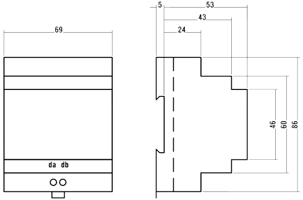
The AFR 31 is designed to be installed on a 35-millimeter DIN strip (DIN EN 50 022).
The AFR 31 works in conjunction with a metering voltage transformer while open delta is connected to auxiliary windings (terminals da, dn). One of pole must be grounded. Before connection.
The open delta configured auxiliary windings may be, together with the AFR 31 Smart Load, used for ground connection protection relay, which is to be connected in parallel to AFR 31 using the protection relay manufacturer’s recommendations. AFR 31 parallel connection does not affect protection relay operation.
| Nominal voltage | 100/3, 110/3, 120/3 VAC |
| Activation voltage | no jumper: 20 VAC 3+4 jumper: 25 VAC ( default ) 1+3 jumper: 30 VAC |
| Activation delay | 4.0 sec ( other values in range 0.5 ÷ 10sec on request ) |
| Protection degree | IP20 |
| Overvoltage class | II |
| Climate category | 5/50/40 |
| Operation / storage temperature | -20°C ÷ 40 °C / -20°C ÷ 70°C |
| Operation / storage humidity | 95 % non-condensing |
| Dimensions / mass | 69 x 86 x 58 mm / 0.05 kg |
| Cover material | polycarbonate |
| Installation | 35 mm DIN bar mount ( DIN EN 50 022 ) |
| Connection | screw terminals, 0.5 ÷ 2.5 mm2 wire cross section |
summary of test report test report
Wireup
Desired activation voltage must be set before installation. Release snap-in latches with an appropriate size screwdriver and remove the instrument cover.
You can set on of three levels according technical parameters table. Default activation voltage level is preset to 25 V. Higher level is suitable for high voltage grids with higher unbalance of parasitic capacities. After setting, and snap in the rear panel back (keep attention to the correct LED light pipe position).
The AFR 31 is designed to be installed on a 35-millimeter DIN strip (DIN EN 50 022) and for indoor use only.
Natural air circulation should be provided inside the distribution board cabinet, and in the instrument’s neighborhood, especially underneath the instrument, no other instrumentation that is source of heat should be installed. The instrument must be installed in indicated position with its terminals oriented down, usually in the measuring and protection control panels.
The AFR 31 works in conjunction with a metering voltage transformer while open delta is connected to auxiliary windings (terminals da, dn) as shown in the wiring diagram below. 2.5 square millimeter copper wire is recommended for the circuit. One of pole must be grounded. Before connection, check the grounding both at the transformer and the load side to avoid unwanted duplicity; otherwise measuring voltage transformers can be short-circuited and destroyed.
The open delta configured auxiliary windings may be, together with the AFR 31 Smart Load, used for ground connection protection relay, which is to be connected in parallel to AFR 31 using the protection relay manufacturer’s recommendations. AFR 31 parallel connection does not affect protection relay operation.
Smart Load wireup diagram in metering voltage transformer auxiliary winding open delta configuration
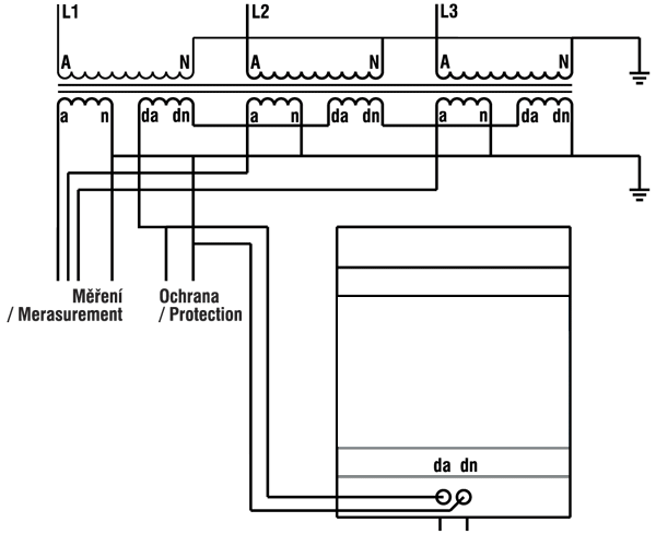
| A, N: | Metering transformer high voltage terminals |
| a, n: | Secondary metering winding |
| da, dn: | Other secondarywinding terminals |
| AFR30: | Smart Load |
| PE |